
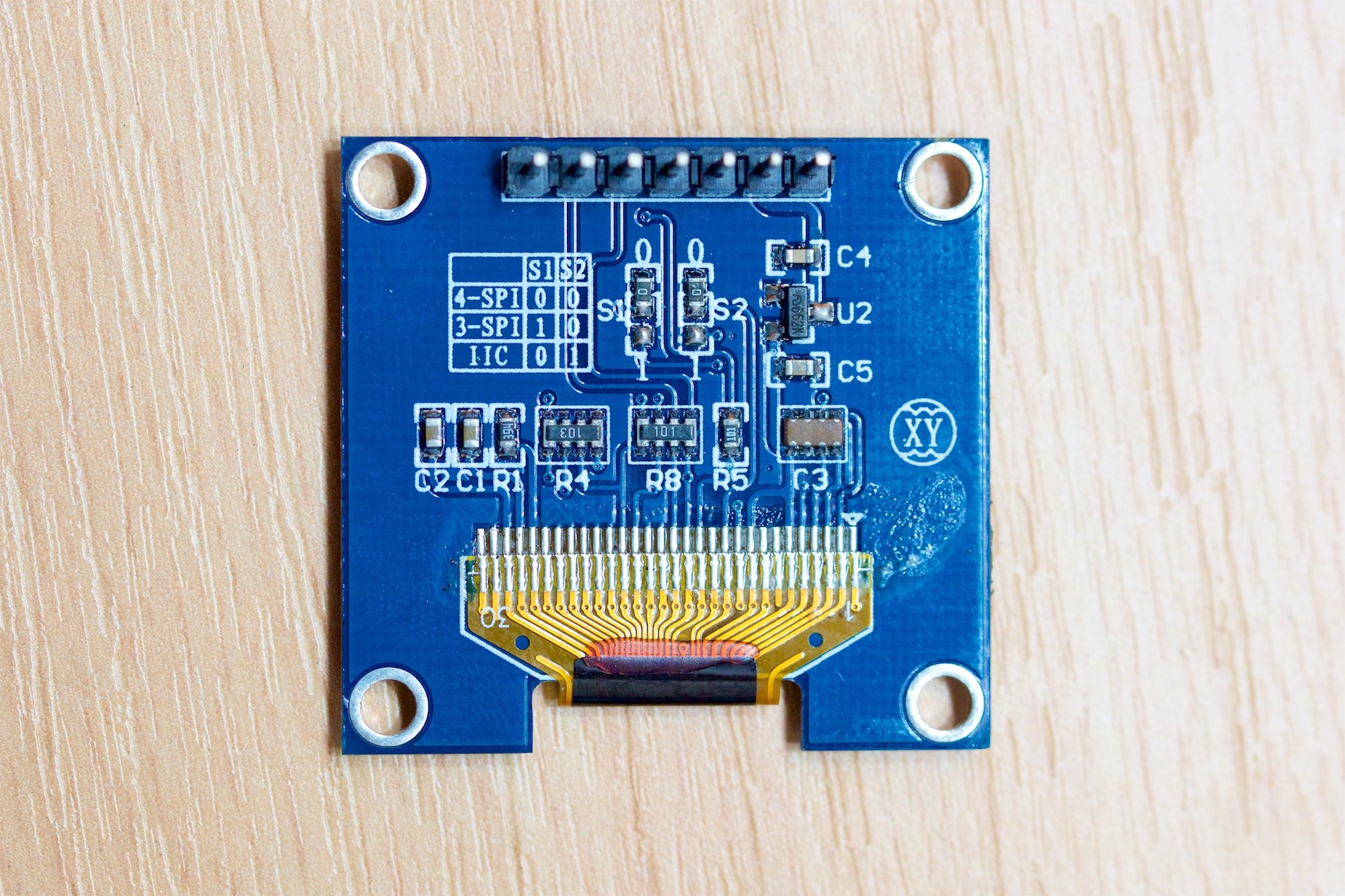
A while ago I had ordered an Arduino OLED display with 128×64 pixels resolution and a blue-white color scheme. It comes preconfigured in 4-SPI mode (S1=0, S2=0) and is basically ready to be used. I’m using an Arduino Uno platform with the lastest Arduino IDE 1.6.7 which has been expanded with the u8glib library from olikraus (https://github.com/olikraus/u8glib/wiki).
When ordering one of these Arduino OLED displays from China you should be expecting to figure out a way to drive them yourself. Often, they provide a small library and code to let you test it, but essentially you might need to integrate a more sophisticated library in your Arduino program. The following code shows you how to enable the u8glib in your code.
#include "U8glib.h"
U8GLIB_SH1106_128X64 u8g(9,10,13,12,11);
The first line loads the actual library header file and the second line creates the actual display instance for you to access. This display is most likely an SH1106 and should be initialized as above. I’ll explain later why you might need to use this instead of another display controller name.

Wiring of the Arduino OLED
There really aren’t that many pins, but if you don’t know where to start, this might actually get really frustrating really soon. (Mainly because you think you actually need to hook up the CS signal, which you don’t 😉 ). While the actual definition of the u8g function looks like this, these pin-names don’t help you at all.
U8GLIB_SH1106_128x64 u8g(sck, mosi, cs, a0 [, reset])
The following wiring list will show you the correct way to connect your OLED display and if you actually use the upper code example, you will need to use pins 9 through 12 to connect the pins in order from left to right, starting with D0.
- D0 -> 9 (sck)
- D1 -> 10 (mosi)
- RST -> 11 (reset)
- DC -> 12 (a0)
- CS -> do not connect (would be 13)
- GND -> GND/0V
- VCC -> 5V/3.3V (depending on your model)
Arduino OLED Display Controller Type and Possible Errors
I’ve mentioned above that you will need to use the SPH1106 display driver controller name when declaring your u8g instance. Some of you may have tried to use the SSD1306 or SSD1309 and you are wondering why it’s not perfect. It will actually show the content on your screen and work, but somehow the content of your x-pixel-columns 0 and 1 are missing and on the right you are seeing a white vertical line or bar. This is the reason to use the SPH1106. If you experience this error even though you are using this controller type name, try one of the following two options as well.
U8GLIB_SSD1306_128X64 u8g(9,10,13,12,11);
U8GLIB_SSD1309_128X64 u8g(9,10,13,12,11);
I hope this little guide will help you get started with your Arduino experiment using the OLED display that you ordered online. Here’s a little quick start source code snippet that you can use to upload to your Arduino. This should run if you connect your display according to the prior list that I posted.
#include "U8glib.h"
U8GLIB_SH1106_128X64 u8g(9,10,13,12,11);

void setup() {
}

void loop() {
  u8g.firstPage();
  do {
    draw();
  } while(u8g.nextPage());
}

void draw() {
  u8g.setFont(u8g_font_unifont);
  u8g.drawStr( 0, 20, "Hello World!");
}
If you enjoy this type of content, I’d love to enjoy a cup of coffee while typing the next one!
